Position of an Object in Water
£0.00
This diagram is a new addition to the site! More information will be added ASAP 🙂
Description
Position of an Object in Water
TRY SOME QUICK QUESTIONS AND ANSWERS TO GET STARTED
About the diagram
Have you already checked out An Introduction to Reflection, Refraction and Dispersion?
It is the opening page of our Reflection, Refraction and Dispersion Series and contains masses of useful information. This is the table of contents:
Overview
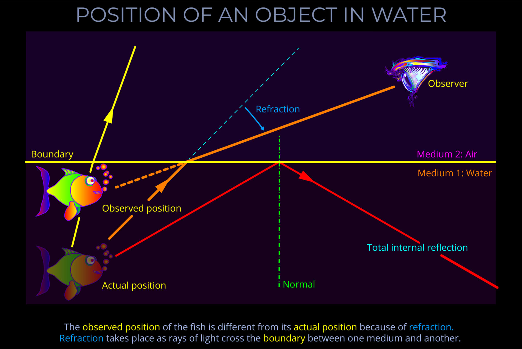
This page explores how the actual position and the observed position of an object (a fish) in water are different from the point of view of an observer looking down from above.
What an observed sees as they look across the boundary between air and water is the result of the combined effects of refraction, reflection and total internal reflection.
To get the most out of this page review the following pages as well:
The diagram
In the diagram, incident light reflects off the body of the fish towards the surface formed by the boundary between water and air.
- The diagram shows that refraction bends the rays of light as they cross into the air.
- The change in direction of the light rays is not obvious to the observer. As a result, the fish appears to be closer to the surface.
- The actual path of the red ray illustrates the change in direction caused by refraction.
- The dotted line illustrates what the observer mistakenly thinks they are seeing.
Remember that:
- Depending on the angle at which the light strikes the underside of the surface, different proportions of light are refracted or reflected.
- Above and angle of 48.60 total internal reflection takes place and none is refracted.
- Total internal reflection means all light reflects off the underside of the surface back into the water.
- Remember that the angle of incidence is always equal to the angle of reflection when rays strike the surface.
What the observer sees
This diagram is particularly concerned with what the observer sees.
- Follow the red coloured ray from the fish to the eye of the observer.
- Because the optical density of air as lower than water it bends away from the normal as it crosses the boundary between water and air
- The observer isn’t aware of this change of direction of the ray.
- Now follow the same ray from the observer’s eye towards the fish.
- The dotted red line shows where the observer believes the fish to be.
Remember that:
- Many rays of light don’t travel towards the observer.
- The diagram shows two orange rays that are reflected off the scales of the fish and travel of in other directions.
- One strikes the surface at almost 900. As a result, it bends a little way from the normal.
- The other ray strikes the surface at more than 48.60. As a result, total internal reflection takes place on no light is refracted.
- Things that we look through, such as reading glasses, binoculars and cameras, contain transparent elements made of glass, polycarbonates and other high-tech plastics designed to refract and reflect light in different ways and for various purposes.
- Our eyes also have optical elements including the cornea, lens and transparent liquids all of which affect how we see the world.
Incident light
Incident light refers to incoming light that is travelling towards an object, surface or medium.
Angle of incidence
- The angle of incidence measures the angle at which incoming light strikes the boundary between two media.
- The angle of incidence is measured between a ray of incoming light and an imaginary line called the normal.
Angles of reflection and refraction
- The angles of reflection and refraction measure the angle to which light bends as it strikes the boundary between different media.
- The angles of reflection and refraction are measured between a ray of light and an imaginary line called the normal.
Refraction
The term refraction refers to the way a light wave changes direction and speed as it travels from one medium to another.
- When light crosses the boundary between two different transparent media it undergoes refraction.
- The effect of refraction is that light changes speed and its direction of travel.
- The change in speed can be calculated if the refractive index is known.
- The index of refraction can be calculated if the speed of light in a vacuum and the speed of light in the medium is known.
- The refractive index of a medium is calculated using the formula: [\large n = \frac{c}{v}] Where n = refractive index, c = speed of light in a vacuum, v = speed of light in a transparent medium.
- The amount that the path of a ray of light bends when it changes direction is calculated using the Law of Refraction (also known as Snell’s law).
Refractive index
-
- The refractive index (also known as the index of refraction) of a transparent medium is a ratio that allows the speed at which light travels through it to be calculated.
- The refractive index of a medium can be calculated using the formula:
Where n = refractive index, c = speed of light in a vacuum, v = speed of light in a transparent medium.
-
-
- When light travels through a vacuum, such as outer space, it travels at its maximum speed of 299,792 kilometres per second.
- When light travels through any other transparent medium it travels more slowly.
- Refractive indices describe the ratio between the speed of light in a vacuum and the speed of light in another medium.
- Most transparent media have a refractive index of between 1 and 2.
- Whilst the refractive index of a vacuum has the value of 1.0, the refractive index for water is 1.333.
- The ratio between them is therefore 1:1.333
- A simple example of a ratio is of mixing concrete using 1 part of cement to 2 part of sand. The ratio is expressed as 1:2, so there is half as much cement as sand because 1 divided by 2 = 0.5.
- If we divide the refractive index for light travelling through a vacuum (1.0) by the refractive index for glass (1.333) we find that light travels at 0.75 the speed of light in a vacuum so at three-quarters of its maximum speed.
-
Reflection
The term reflection refers to the fact that when light strikes any object some wavelengths are absorbed whilst others simply bounce off the surface. Reflection describes what happens to the wavelengths that bounce back and change direction.
-
- Reflection takes place when incoming light strikes the surface of a medium, some wavelengths are obstructed, and the wavefront bounces off and returns into the medium from which it originated.
-
- Reflection obeys the following rules:
- The incident ray, the reflected ray and the normal to the reflection surface all lie in the same plane.
- The angle which the incident ray makes with the normal is equal to the angle which the reflected ray makes with the same normal.
- The reflected ray and the incident ray are on the opposite sides of the normal.
- Reflection takes place when light is neither absorbed by an opaque medium nor transmitted through a transparent medium.
- When light reflects off a surface, the angle of incidence of an incoming ray as it approaches the surface is equal to the angle of reflection.
- If the reflecting surface is very smooth, the reflection of light is called specular or regular reflection.
- Specular reflection occurs when light waves reflect off a smooth surface such as a mirror. The arrangement of the waves remains the same and an image of objects that the light has already encountered become visible to an observer.
- Diffuse reflection takes place when light reflects off a rough surface. In this case, scattering takes place and waves are reflected randomly in all directions and so no image is produced.
- Reflection is independent of the optical density of the medium through which the incident light is propagating or of the medium it bounces off.
- Reflection obeys the following rules:
Some key terms
In physics and optics, a medium refers to any material through which light or other electromagnetic waves can travel. It’s essentially a substance that acts as a carrier for these waves.
- Light is a form of electromagnetic radiation, which travels in the form of waves. These waves consist of oscillating electric and magnetic fields.
- The properties of the medium, such as its density and composition, influence how light propagates through it.
- Different mediums can affect the speed, direction, and behaviour of light waves. For instance, light travels slower in water compared to a vacuum.
- Examples of Mediums:
- Transparent: Materials like air, glass, and water allow most light to pass through, with minimal absorption or scattering. These are good examples of mediums for light propagation.
- Translucent: Some materials, like frosted glass or thin paper, partially transmit light. They allow some light to pass through while diffusing or scattering the rest.
- Opaque: Materials like wood or metal block light completely. They don’t allow any light to travel through them.
The angle of refraction measures the angle to which light bends as it passes across the boundary between different media.
- The angle of refraction is measured between a ray of light and an imaginary line called the normal.
- In optics, the normal is a line drawn on a ray diagram perpendicular to, so at a right angle to (900), the boundary between two media.
- See this diagram for an explanation: Refraction of a ray of light
- If the boundary between the media is curved, the normal is drawn perpendicular to the boundary.
A wave diagram is a graphic representation, using specific drawing rules and labels, that depicts variations in the characteristics of light waves. These characteristics include changes in wavelength, frequency, amplitude, speed of light and propagation direction.
- A wave diagram provides a visual representation of how a wave behaves when interacting with various media or objects.
- The purpose of a wave diagram is to illustrate optical phenomena, including reflection, refraction, dispersion, and diffraction.
- Wave diagrams can be useful in both theoretical and practical applications, such as understanding the basics of the physics of light or when designing complex optical systems.
As light crosses the boundary between two transparent media, the law of refraction (Snell’s law) states the relationship between the angle of incidence and angle of refraction of the light with reference to the refractive indices of both media as follows:
When electromagnetic radiation (light) of a specific frequency crosses the interface of any given pair of media, the ratio of the sines of the angles of incidence and the sines of the angles of refraction is a constant in every case.
- Snell’s law deals with the fact that for an incident ray approaching the boundary of two media, the sine of the angle of incidence multiplied by the index of refraction of the first medium is equal to the sine of the angle of refraction multiplied by the index of refraction of the second medium.
- Snell’s law deals with the fact that the sine of the angle of incidence to the sine of the angle of refraction is constant when a light ray passes across the boundary from one medium to another.
- Snell’s law can be used to calculate the angle of incidence or refraction associated with the use of lenses, prisms and other everyday materials.
- When using Snell’s law:
- The angles of incidence and refraction are measured between the direction of a ray of light and the normal – where the normal is an imaginary line drawn on a ray diagram perpendicular to, so at a right angle to (900), to the boundary between two media.
- The wavelength of the incident light is accounted for.
- The refractive indices used are selected for the pair of media concerned.
- The speed of light is expressed in metres per second (m/s).
If one line is normal to another, then it is at right angles to it.
In geometry, normal (a or the normal) refers to a line drawn perpendicular to a given line, plane or surface.
- How the normal appears in a geometric drawing depends on the circumstances:
- When light strikes a flat surface or plane, or the boundary between two surfaces, the normal is drawn perpendicular to the surface, forming a right angle (90°) with it.
- Expressed more formally, in optics, the normal is a geometric construct, a line drawn perpendicular to the interface between two media at the point of contact. This conceptually defined reference line is crucial for characterizing various light-matter interactions, such as reflection, refraction, and absorption.
- When dealing with curved surfaces, such as those found on spheres or other three-dimensional objects, determining the normal requires a slightly different approach. Instead of simply drawing a line perpendicular to the surface as with a flat plane, draw the normal straight up from the point where light hits the surface.
- When considering a sphere, the normal line passes through the centre of the sphere. This is because, regardless of where light enters or exits the sphere, the normal represents the direction perpendicular to the surface at that point.
The angle of incidence measures the angle at which incoming light strikes a surface.
- The angle of incidence is measured between a ray of incoming light and an imaginary line called the normal.
- See this diagram for an explanation: Reflection of a ray of light
- In optics, the normal is a line drawn on a ray diagram perpendicular to, so at a right angle to (900), the boundary between two media.
- If the boundary between the media is curved, then the normal is drawn at a tangent to the boundary.
The angle of reflection measures the angle at which reflected light bounces off a surface.
- The angle of reflection is measured between a ray of light which has been reflected off a surface and an imaginary line called the normal.
- See this diagram for an explanation: Reflection of a ray of light
- In optics, the normal is a line drawn on a ray diagram perpendicular to, so at a right angle to (900), the boundary between two media.
- If the boundary between the media is curved then the normal is drawn perpendicular to the boundary.
Diagrams are free to download
Related products
-
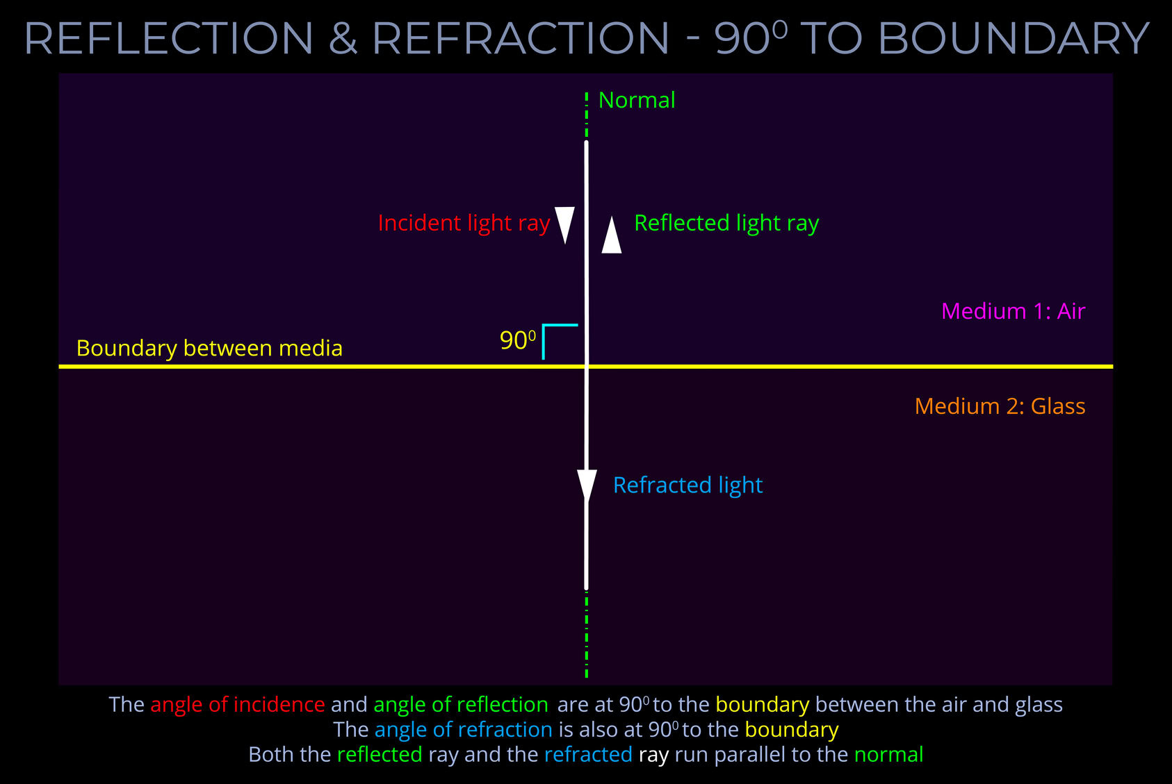
Reflection & Refraction – 90 deg to Boundary
£0.00 Select options This product has multiple variants. The options may be chosen on the product page -
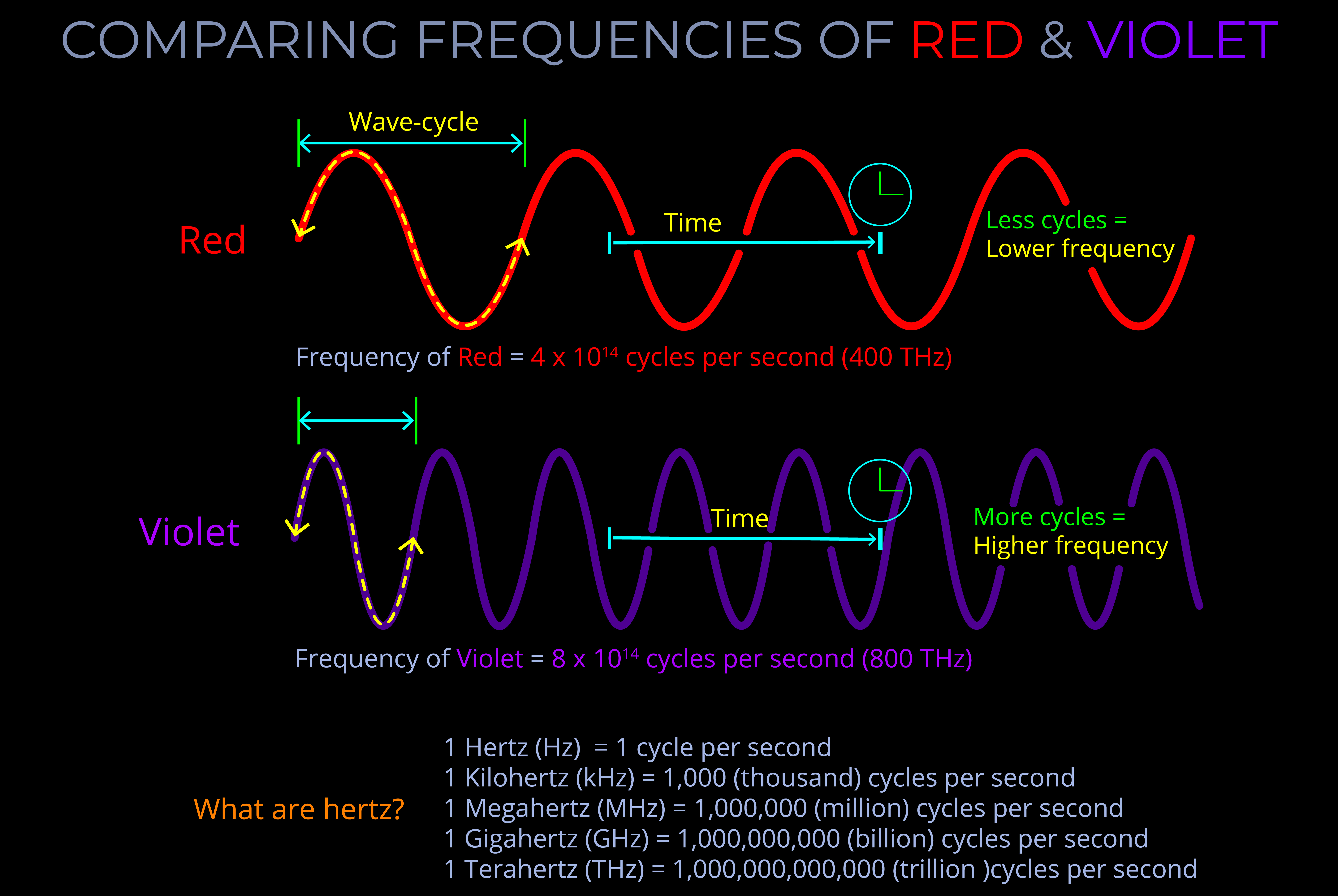
Comparing Frequencies of Red & Violet
£0.00 Select options This product has multiple variants. The options may be chosen on the product page -
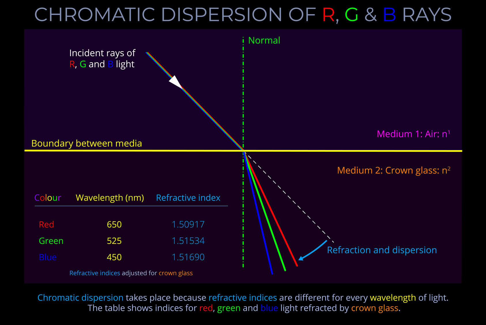
Chromatic Dispersion of R G & B Rays
£0.00 Select options This product has multiple variants. The options may be chosen on the product page