Reflection & Total Internal Reflection
£0.00
This diagram is a new addition to the site! More information will be added ASAP 🙂
Description
Reflection & Total Internal Reflection
TRY SOME QUICK QUESTIONS AND ANSWERS TO GET STARTED
About the diagram
Have you already checked out An Introduction to Reflection, Refraction and Dispersion?
It is the opening page of our Reflection, Refraction and Dispersion Series and contains masses of useful information. This is the table of contents:
The diagram
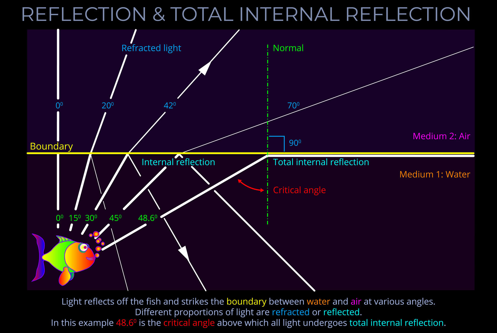
- In this diagram sunlight or artificial light travelling through water reflects upwards off the body of the fish.
- For clarities sake, the diagram doesn’t show light travelling towards the fish.
- Check out our diagram dealing with the way parallel incident light rays scatter in different directions as they are reflected off the body of the fish: Sunlight Reflects off a Fish in Water
- Notice how the light reflected off the fish and towards the surface is incident to the boundary between water and air.
- As the incident light strikes the surface a proportion is refracted as it crosses the boundary into the air and a proportion is reflected off the surface back into the water.
- The diagram demonstrates the paths taken for a ray travelling parallel to the normal and striking the boundary at right angles and for rays at angles of 150, 300, 450 to the normal.
- Notice that the amount of light that is reflected increases as the angle increases but that above 48.60 total internal reflection takes place and all the light is reflected.
- Depending on the angle at which the light strikes the surface, different proportions are refracted or reflected.
- The ratio of the reflected intensity to the incident intensity is called the reflectance (R) and the ratio of the transmitted intensity to the incident intensity is called the transmittance (T). Energy conservation requires that R + T = 1 (if there is no absorption).
- The reflectance of the surface of a material is its effectiveness at reflecting radiant energy.
- The transmittance of the surface of a material is its effectiveness at transmitting radiant energy.
Some key terms
A wave diagram is a graphic representation, using specific drawing rules and labels, that depicts variations in the characteristics of light waves. These characteristics include changes in wavelength, frequency, amplitude, speed of light and propagation direction.
- A wave diagram provides a visual representation of how a wave behaves when interacting with various media or objects.
- The purpose of a wave diagram is to illustrate optical phenomena, including reflection, refraction, dispersion, and diffraction.
- Wave diagrams can be useful in both theoretical and practical applications, such as understanding the basics of the physics of light or when designing complex optical systems.
The angle of reflection measures the angle at which reflected light bounces off a surface.
- The angle of reflection is measured between a ray of light which has been reflected off a surface and an imaginary line called the normal.
- See this diagram for an explanation: Reflection of a ray of light
- In optics, the normal is a line drawn on a ray diagram perpendicular to, so at a right angle to (900), the boundary between two media.
- If the boundary between the media is curved then the normal is drawn perpendicular to the boundary.
Refraction refers to the way that electromagnetic radiation (light) changes speed and direction as it travels across the boundary between one transparent medium and another.
- Light bends towards the normal and slows down when it moves from a fast medium (like air) to a slower medium (like water).
- Light bends away from the normal and speeds up when it moves from a slow medium (like diamond) to a faster medium (like glass).
- These phenomena are governed by Snell’s law, which describes the relationship between the angles of incidence and refraction.
- The refractive index (index of refraction) of a medium indicates how much the speed and direction of light are altered when travelling in or out of a medium.
- It is calculated by dividing the speed of light in a vacuum by the speed of light in the material.
- Snell’s law relates the angles of incidence and refraction to the refractive indices of the two media involved.
- Snell’s law states that the ratio of the sine of the angle of incidence to the sine of the angle of refraction is equal to the ratio of the refractive indices.
The angle of incidence measures the angle at which incoming light strikes a surface.
- The angle of incidence is measured between a ray of incoming light and an imaginary line called the normal.
- See this diagram for an explanation: Reflection of a ray of light
- In optics, the normal is a line drawn on a ray diagram perpendicular to, so at a right angle to (900), the boundary between two media.
- If the boundary between the media is curved, then the normal is drawn at a tangent to the boundary.
The angle of refraction measures the angle to which light bends as it passes across the boundary between different media.
- The angle of refraction is measured between a ray of light and an imaginary line called the normal.
- In optics, the normal is a line drawn on a ray diagram perpendicular to, so at a right angle to (900), the boundary between two media.
- See this diagram for an explanation: Refraction of a ray of light
- If the boundary between the media is curved, the normal is drawn perpendicular to the boundary.
Reflection is the process where light rebounds from a surface into the medium it came from, instead of being absorbed by an opaque material or transmitted through a transparent one.
- The three laws of reflection are as follows:
- When light hits a reflective surface, the incoming light, the reflected light, and an imaginary line perpendicular to the surface (called the “normal line”) are all in the same flat area.
- The angle between the incoming light and the normal line is the same as the angle between the reflected light and the normal line. In other words, light bounces off the surface at the same angle as it came in.
- The incoming and reflected light are mirror images of each other when looking along the normal line. If you were to fold the flat area along the normal line, the incoming light would line up with the reflected light.
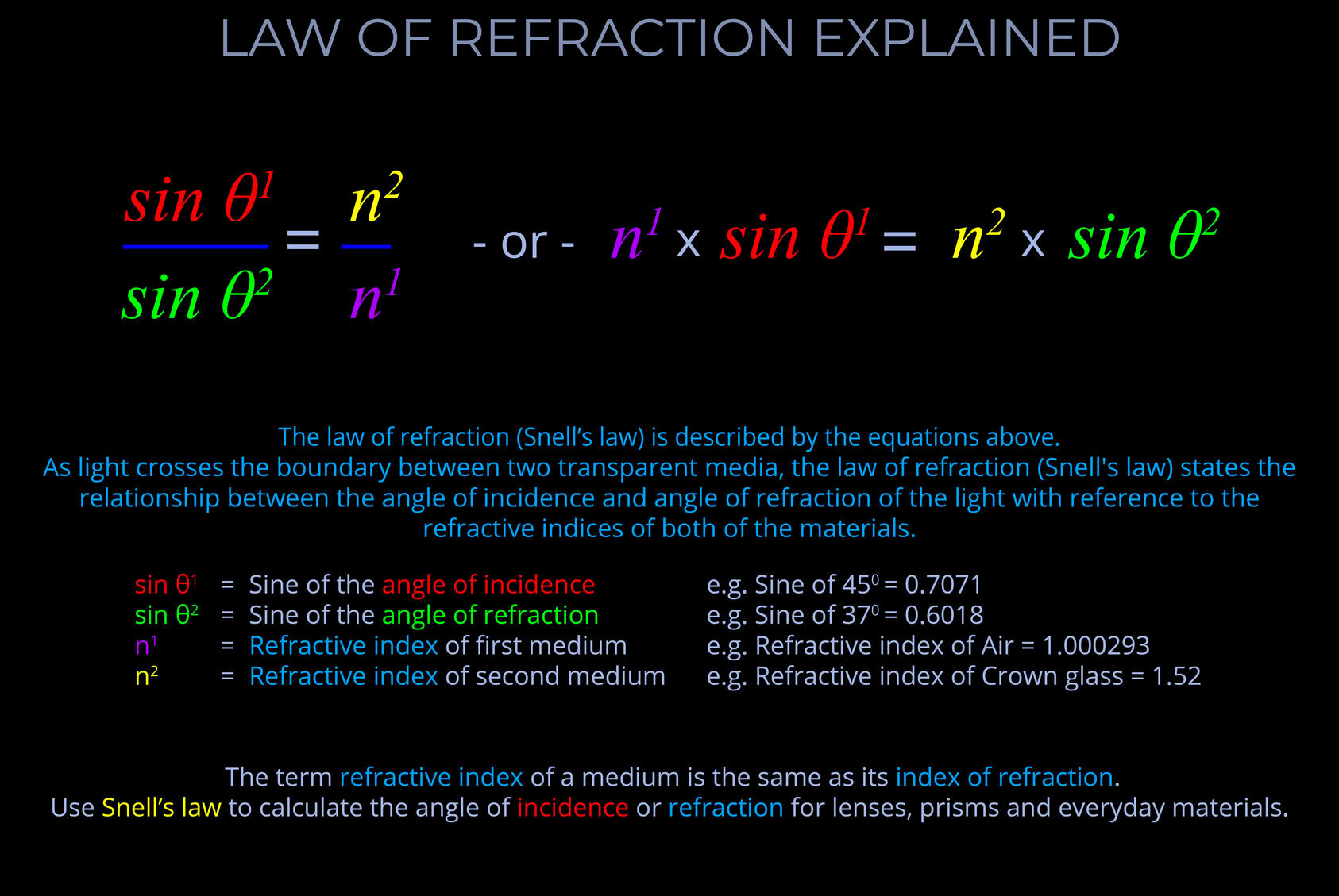
As light crosses the boundary between two transparent media, the law of refraction (Snell’s law) states the relationship between the angle of incidence and angle of refraction of the light with reference to the refractive indices of both media as follows:
When electromagnetic radiation (light) of a specific frequency crosses the interface of any given pair of media, the ratio of the sines of the angles of incidence and the sines of the angles of refraction is a constant in every case.
- Snell’s law deals with the fact that for an incident ray approaching the boundary of two media, the sine of the angle of incidence multiplied by the index of refraction of the first medium is equal to the sine of the angle of refraction multiplied by the index of refraction of the second medium.
- Snell’s law deals with the fact that the sine of the angle of incidence to the sine of the angle of refraction is constant when a light ray passes across the boundary from one medium to another.
- Snell’s law can be used to calculate the angle of incidence or refraction associated with the use of lenses, prisms and other everyday materials.
- When using Snell’s law:
- The angles of incidence and refraction are measured between the direction of a ray of light and the normal – where the normal is an imaginary line drawn on a ray diagram perpendicular to, so at a right angle to (900), to the boundary between two media.
- The wavelength of the incident light is accounted for.
- The refractive indices used are selected for the pair of media concerned.
- The speed of light is expressed in metres per second (m/s).
If one line is normal to another, then it is at right angles to it.
In geometry, normal (a or the normal) refers to a line drawn perpendicular to a given line, plane or surface.
- How the normal appears in a geometric drawing depends on the circumstances:
- When light strikes a flat surface or plane, or the boundary between two surfaces, the normal is drawn perpendicular to the surface, forming a right angle (90°) with it.
- Expressed more formally, in optics, the normal is a geometric construct, a line drawn perpendicular to the interface between two media at the point of contact. This conceptually defined reference line is crucial for characterizing various light-matter interactions, such as reflection, refraction, and absorption.
- When dealing with curved surfaces, such as those found on spheres or other three-dimensional objects, determining the normal requires a slightly different approach. Instead of simply drawing a line perpendicular to the surface as with a flat plane, draw the normal straight up from the point where light hits the surface.
- When considering a sphere, the normal line passes through the centre of the sphere. This is because, regardless of where light enters or exits the sphere, the normal represents the direction perpendicular to the surface at that point.


